Power factor improvement using capacitor bank pdf
Improvement of Power Factor for Industrial Plant with Automatic Capacitor Bank Marlar Thein Oo, Ei Ei Cho Abstract-This paper is intended to uplift the technological
(2) Static capacitors or Capacitor Bank synchronous condensers, can produce reactive power and the production of reactive power can be regulated. Due to this regulating advantage, the synchronous condensers are very suitable for correcting power factor of the system, but this equipment is quite expensive compared to static capacitors. That is why synchronous condensers, are justified to use
controllable with a properly designed power factor improvement capacitors system. The power factor correction The power factor correction obtained by using capacitor banks to generate locally the reactive energy necessary for the transfer of electrical
enclosed medium-voltage capacitor banks are designed for systems such as industrial, commercial, and utility power systems involving motors, feeder circuits, and transmission and distribution lines where power factor improvement is required . Metal-enclosed medium-voltage power factor correction system. 2 Technical Data TD02607011E Effective December 2016 Metal-enclosed medium-voltage power
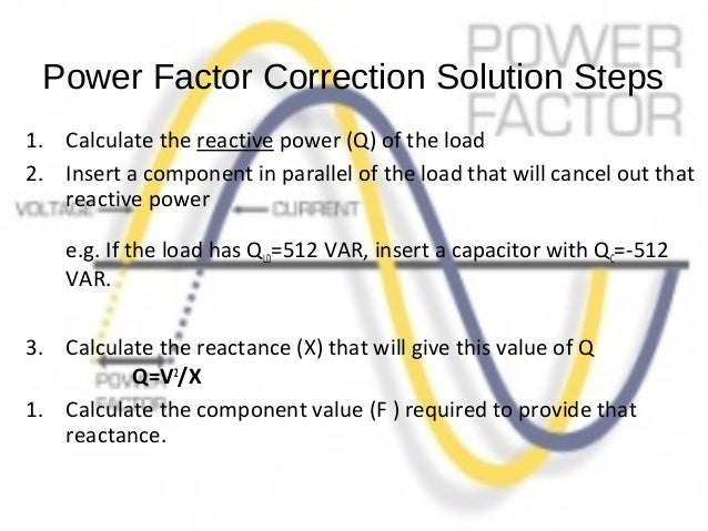
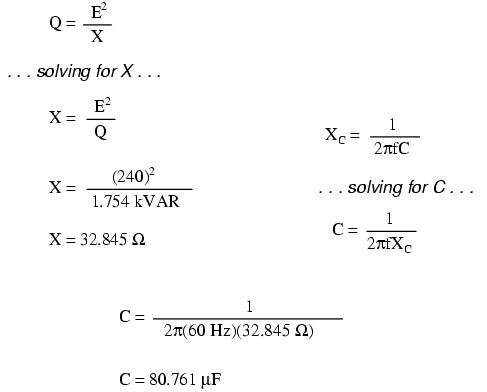
of power factor correction using PIC microcontroller chip, determine the power factor of the loaded power The actual capacitor in farads of a capacitor bank can be calculated using the following equation:[3] C= VAR/2πf*V R 2 Where, VAR = capacitor unit var rating
BOTTOM LINE ON Understanding Power Factor and How it Affects Your Electric Bill z Very small charge with penalty most customer have no Power Factor Penalty z None or very small savings or possible increase cost when using Power Factor Correction Devices .
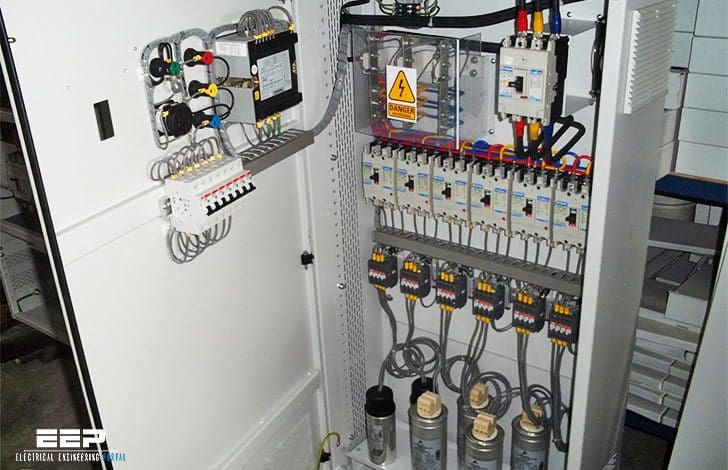
C100 series Automatic Power Factor Correction Automatic Capacior Bank Assembly system. 208 to 600 Volts fuses) are built into a compact steel enclosure. load, check that the automatic capacitor bank The Reactive Power Solution The Gentec C100 Automatic capacitor banks are used for central power factor correction at main and group distribution boards. Power factor correction means that reactive
-3-2. ECONOMIC EFFECT OF COMPENSATION 1. INTRODUCTION Fig. 1 The apparent power of a network can be reduced by means of power factor correction (PFC).
The size of capacitor in kVAR is the kW multiplied by factor in table to improve from existing power factor to proposed power factor. Check the others Examples below. Check the others Examples below.
This paper deals with shunt capacitor bank designing for power factor improvement and helped to reduce the electricity bill of an agro based plant (Jagannath Cotton Mill) of a farmer located at Rayagada District, Odisha, India.
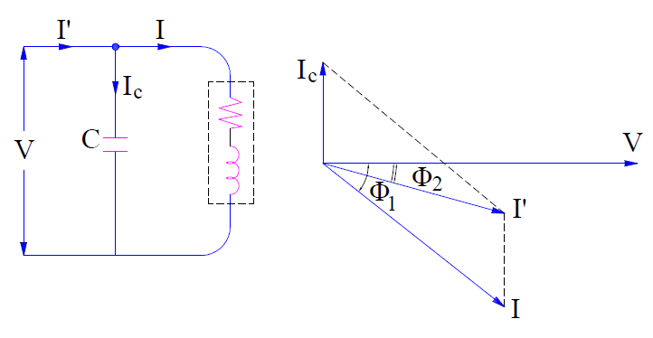
To illustrate the power factor improvement by a capacitor, consider a single *phase load taking lagging current I at a power factor cos φ 1 as shown in Fig. 6.3. The capacitor C is connected in parallel with the load.
Automatic Power factor correction Using Capacitive bank
Benefits of Power Factor Correction Power Factor
Power factor correction is particularly important for dc drives because phasing back of the SCRs results in relatively poor power factor, especially when the motor is at reduced speeds. Additional transformer capacity is required to handle the poor power factor conditions (and the harmonics) and more utilities are charging a power factor penalty that can significantly impact the total bill for
The power factor improvement using capacitor bank is very common in an industrial installation. Most Economical Power Factor The investment in power factor equipment is relatively high as the p.f. approaches to unity because capacitors of much larger rating are required for bringing about the same improvement in p.f. when it is near unity than when it is low.
This paper is based on novel power factor improvement of a 3-phase induction motor using switched capacitor banks with Programmable Logic controller which incorporates development of the hardware
power factor correction and control of electrical network quality international version agroup brand ex216012_at_1couv-21_en.indd 1 15/11/2016 09:37
The basic principle of power factor improvement is to inject a leading current into the circuit so as to neutralize the effect of lagging current. The power factor may be improved by using Static capacitors or synchronous motors.
2 Figure 2 Capacitor bank supplying the reactive power required by the loads Figure 2 is a low voltage capacitor bank. A common reason for poor power factor is operating motors at
Benefits of Power Factor Correction. There are numerous benefits to be gained through power factor correction. These benefits range from reduced demand charges on your power system to increased load carrying capabilities in your existing circuits and overall reduced power system loses.
Low Voltage Power Capacitors CAPACITOR SELECTION TABLE FOR POWER FACTOR CORRECTION OF ELECTRICAL MOTORS Reactive power is required by an asynchronous motor for the magnetic field. The amount of reactive power consumption of a motor depends on various parameters such as power rating, loading, rated speed, and design. The capacitor output should be maximum 90 % of the apparent power …
Power factor is the ratio of watts (true power) to VA (volt-amperes, also called apparent power). When the load is resistive When the load is resistive only, the power factor is one, or unity, because the voltage waveform and the current waveform are in phase.
How to improve the power factor? It’s quite simple. By installing capacitors or capacitor banks. Improving the power factor of an electrical installation consists of giving it the means to “produce” a certain proportion of the reactive energy it consumes itself.
Static Var Generators (SVG) The Sinexcel SVG represents the latest generation technology in Power Factor Correction solutions. By eliminating the need for switched capacitors and providing dynamic step-less compensation, the SVG is a totally modern solution that offers high performance in a compact package and requires very low maintenance.
Power Factor Improvement for Pumping Stations using Capacitor Banks As three-phase induction motors are the main prime mover of pumping stations and considered the most widely used electrical motors due to their reliability, ease of maintenance.
Power factor improvement Application guide Low Voltage Products. 2 Table of contents Power factor improvement 3 Basics of power factor 5 Options and solutions 6 Options and solutions, applications and installation 7 Applications and installation 9 Low voltage capacitor construction 11 Sizing capacitors 14 Harmonics 16 Harmonics filtering 17 Appendix Table of contents. Power factor
factor correction circuit consist of capacitor bank that would normally be switched on or off depending on the reactive demand from the load [4]. Shunt capacitors are used for loss reduction, voltage profile improvement and

1 6 9 10 2 Capacitors for the World In 2009, Siemens extended its product portfolio to deliver high-voltage power capacitors and capacitor banks to cus-
Usually, the power factor correction can be done by using the capacitor and the synchronous motor in the circuit.The power factor correction will not change the amount of true power, but it will reduce the apparent power and the total current drawn from the load.
– Accurate and reliable power factor control of a system even in presence of high current and voltage harmonic content –Warrants optimal capacitor use for increased life using ratio-
To improve the power factor to 0.93 (i.e. tan φ = 0.4), the reactive power of the capacitor bank must be: Qc = 100 (0.88 – 0.4) = 48 kvar The selected level of compensation and the calculation of rating for the capacitor bank depend on the particular installation.
What is Power Factor Correction? Definition & Methods
The power factor correction obtained by using capacitor banks to generate locally the reactive energy necessary for the transfer of electrical useful power, allows a better and more rational technical-economical management of the plants. There are so many industries around the world and so are in Myanmar. Most of the industrial plants are using the inductive loads in infrastructure such as
different advantages of using Power Factor correction systems. Recommendations to push users to install power factors correction will be given. Optimal use of capacitor banks through better control and maintenance can improve the benefits and the savings. Development of communication towards users about the benefits of power factor correction is one action to expand the use of these systems
Power factor correction capacitors reduce the total current supplied by the Electricity Supply Company to the load and as a result the distribution system capacity is increased.
18/01/2013 · Calculate Active and Reactive Power of System. Calculate Leading Kvar of system. Calculate Kvar/Phase. Calculate Size of Capacitor for Power Factor Improvements. Calculate Size of Main Fuse of Capacitor Bank Calculate Size of Main Circuit Breaker Calculate Thermal/Magnetic Setting of Circuit Breaker. Calculate Max.Demand/KVA Demand
Also note that after the power factor improvement, the circuit current would be less than from the low power factor circuit current. Also, before and after the power factor improvement, the active component of current would be same in that circuit because capacitor eliminates only the re-active component of current.
transformers, and reactors and capacitive loads are capacitors, When power factor is improved, automatically energy will variable or fixed capacitor banks, motor starting capacitors, be saved A power factor is the goal of any electrical utility generators, and synchronous motors. company since if the power factor is less than one, they Low power factor is not that much problem in domestic’s
The power factor correction obtained by using capacitor banks to generate locally the reactive energy necessary for the transfer of electrical useful power, allows a better and more rational technical-economical management of the plants. Moreover, the present spreading of direct current users, such as electronic circuits and electric drives, involve the generation of current harmonics which
Choices for the power factor correction solutions range from passive circuits to a variety of active circuits. Depending on Depending on the power level and other specifics of the application, the appropriate solution will differ.
Capacitor bank for the respective load is triggered by using PLC, which connects the capacitor bank parallel to the load and thereby bringing the power factor nearly to unity. The speed of the
power factor correction. The use of SCBs has increased because they are relatively inexpensive, Its installation has other beneficial effects on the system such as: improvement of the voltage at the load, better voltage regulation (if they were adequately designed), reduction of losses and reduction or postponement of investments in transmission. The main disadvantage of SCB is that its – hp 8300 elite small form factor desktop manual The main objective of this paper is studying the power factor improvement in El sadaa Pumping Station because of its low operating efficiency which goes from 20 % to 25 %and calculating penalty, ponus and savings in each cases. The correction is achieved by the addition of capacitor banks in parallel with the connected motor circuits and can be applied to the starter, applied at the
Capacitor banks improve Power Factor Correction and help to avoid reactive energy penalties charged by the utility. Capacitor banks can be connected to your facility’s power infrastructure installation at the medium voltage (MV) substation, low voltage (LV) main switchboard, LV secondary switchboard or machine terminals.
Power factor improvement is very useful in any installation as low power factor when corrected, leads to consequent saving in charges, by way of reduced demand charges, and lesser low power factor …
Power System, Power Factor Improvement, Capacitor, Embedded System. 1. Introduction . Most of the consumers consumed the electricity for the purpose of inductive load. The inductive is act as a load lagging power factor. The result of lagging power factor increases the power losses in the power system. The reactive power is compensated by real power by using suitable value of capacitors. …
Chapter 3 Improvement of Load Power Factor Using FACTS Controllers Ph.D Thesis submitted to Jawaharlal Nehru Technological University Anantapur 40 CHAPTER 3 IMPROVEMENT OF LOAD POWER FACTOR USING FACTS CONTROLLERS 3.1 INTRODUCTION The low power factor effects on transmission line, switchgear, transformers etc. It is observed that if the power plant works on low power factor…
Improvement of Load Power Factor by Using Capacitor Ahmad Yani1 1(Faculty of Electrical Engineering, STT-Harapan, Medan, Capacitor breaker is used to protect the cable installation from the breaker to the capacitor bank and also the capacitor itself. The capacity breaker used is 1.5 times nominal current with Im = 10xIr. To calculate the amount of current, the formula can be used is In
Power factor Improvement (Easiest way ever) Hi there! With a very important tutorial.. I hope you will find it very useful because I have already spent two days to prepare this article.
deals with the problem of power factor improvement. Capacitor bank connected in shunt helps in maintaining the power factor closer to unity. They improve the electrical supply quality and increase the efficiency of the system. Also the line losses are also reduced. Shunt capacitor banks are less costly and can be installed anywhere. This paper deals with shunt capacitor bank designing for
With power factor improvement capacitors installed and the power factor improved to 0.95, the KVA requirement drops to 105KVA while the reactive required is now at 33KVAR, the balance of 67KVAR is now being supplied by the capacitor with significant impact on utility bills.
Improving power factor by reducing the kVAr load requires the use of power factor equipment which operate at a leading power factor such as: • Synchronous motors which are either over-excited or under loaded with full excitation so they will supply kVAr to the electrical system.
This paper is based on novel power factor improvement of a 3-phase induction motor using switched capacitor banks with Programmable Logic controller which incorporates development of …
By installing capacitor bank the Power Factor is improved and the value becomes nearer to the 0.9 to 0.95 thus minimizing the line losses and improving the efficiency of electrical power system. Thus by using APFC system the efficiency of the system is highly increased. VI. FUTURE ENHANCEMENTS Automatic correction of the power factor using the capacitive load banks is very efficient because it
CAPACITOR SWITCHING TRANSIENT MODELING AND ANALYSIS ON AN ELECTRICAL UTILITY DISTRIBUTION SYSTEM USING SIMULINK SOFTWARE The quality of electric power has been a constant topic of study, mainly because inherent problems to it can bring great economic losses in industrial processes. Among the factors that affect power quality, those related to transients originated from capacitor bank …
Power Factor Improvement of Induction Motor by Using Capacitors ,Kurukshetra Universtiy Abstract— This paper describes the improvement of power factor of an induction motor by using capacitor bank. When power factor is improved, automatically energy will be saved A power factor is the goal of any electrical utility company since if the power factor is less than one, they have to …
We have to increase the power factor using switchable capacitor bank so as to keep the voltage regulation within limits. The capacitor bank reduces the VAR flow by partly
Shunt capacitor banks are primarily used to improve the power factor in the network. They also improve the voltage stability and reduce network losses. Improving the power factor also means a higher power transmission capability and increased control of the power flow.
29/11/2011 · MOSFET, Transistor, Power Transistor, IGBT, SCR, TRIAC, Relays etc. We also develop IEEE projects like IEEE-2016, IEEE-2017 Student projects along with modifications. Automatic Power factor
Practical Power Factor Correction Chapter 11 – Power Factor When the need arises to correct for poor power factor in an AC power system , you probably won’t have the luxury of knowing the load’s exact inductance in henrys to use for your calculations.
Power Factor Correction by Static Capacitors Circuit Globe
power electronic based devices is increasing, it leads to designing more and more capacitor bank. Shunt capacitor banks are Shunt capacitor banks are used to improve the quality of the electrical supply and the operation of the power system. .
Dimensioning of the capacitor bank. For the dimensioning of the capacitor bank to be installed in order to improve the power factor of a plant, it is necessary to calculate correctly the power factor according to the consumption or to the load cycle of the plant.
the apparent power is high and the power factor is low. Situation with connected capacitor banks To improve the network conditions, a 1100 kvar capacitor bank at 20 kV is connected
Shunt capacitor banks to improve the power factor in the

Power Factor Improvement for Industrial Load by using
Capacitor Bank Designing for Power Factor Improvement
A Method of Finding Capacitor Value for Power Factor
Improvement of Power Factor for Industrial Plant with

Improvement of Load Power Factor by Using Capacitor
Power Factor Correction of Three Phase Induction Motor
– How capacitors improve the power factor and how to
ENERGY EFFICIENCY IMPROVEMENT THROUGH OPTIMIZATION

Improvement of Load Power Factor Using FACTS Controllers
Implementation of Thyristor Switched Capacitors for Power
How to Find Capacitor Size in kVAR & F for Pf Improvement
Low Voltage Products Power factor improvement Application
-3-2. ECONOMIC EFFECT OF COMPENSATION 1. INTRODUCTION Fig. 1 The apparent power of a network can be reduced by means of power factor correction (PFC).
Power factor Improvement (Easiest way ever) Hi there! With a very important tutorial.. I hope you will find it very useful because I have already spent two days to prepare this article.
The size of capacitor in kVAR is the kW multiplied by factor in table to improve from existing power factor to proposed power factor. Check the others Examples below. Check the others Examples below.
Power factor correction capacitors reduce the total current supplied by the Electricity Supply Company to the load and as a result the distribution system capacity is increased.
Power factor correction is particularly important for dc drives because phasing back of the SCRs results in relatively poor power factor, especially when the motor is at reduced speeds. Additional transformer capacity is required to handle the poor power factor conditions (and the harmonics) and more utilities are charging a power factor penalty that can significantly impact the total bill for
– Accurate and reliable power factor control of a system even in presence of high current and voltage harmonic content –Warrants optimal capacitor use for increased life using ratio-
C100 series Automatic Power Factor Correction Automatic Capacior Bank Assembly system. 208 to 600 Volts fuses) are built into a compact steel enclosure. load, check that the automatic capacitor bank The Reactive Power Solution The Gentec C100 Automatic capacitor banks are used for central power factor correction at main and group distribution boards. Power factor correction means that reactive
Practical Power Factor Correction Chapter 11 – Power Factor When the need arises to correct for poor power factor in an AC power system , you probably won’t have the luxury of knowing the load’s exact inductance in henrys to use for your calculations.
Power System, Power Factor Improvement, Capacitor, Embedded System. 1. Introduction . Most of the consumers consumed the electricity for the purpose of inductive load. The inductive is act as a load lagging power factor. The result of lagging power factor increases the power losses in the power system. The reactive power is compensated by real power by using suitable value of capacitors. …
Power Factor Correction of Three Phase Induction Motor
(PDF) Power Factor Correction of Inductive Loads using PLC
The basic principle of power factor improvement is to inject a leading current into the circuit so as to neutralize the effect of lagging current. The power factor may be improved by using Static capacitors or synchronous motors.
controllable with a properly designed power factor improvement capacitors system. The power factor correction The power factor correction obtained by using capacitor banks to generate locally the reactive energy necessary for the transfer of electrical
power electronic based devices is increasing, it leads to designing more and more capacitor bank. Shunt capacitor banks are Shunt capacitor banks are used to improve the quality of the electrical supply and the operation of the power system. .
Capacitor banks improve Power Factor Correction and help to avoid reactive energy penalties charged by the utility. Capacitor banks can be connected to your facility’s power infrastructure installation at the medium voltage (MV) substation, low voltage (LV) main switchboard, LV secondary switchboard or machine terminals.
What is Power Factor Correction? Definition & Methods
Automatic Power factor correction Using Capacitive bank
The power factor correction obtained by using capacitor banks to generate locally the reactive energy necessary for the transfer of electrical useful power, allows a better and more rational technical-economical management of the plants. Moreover, the present spreading of direct current users, such as electronic circuits and electric drives, involve the generation of current harmonics which
The power factor improvement using capacitor bank is very common in an industrial installation. Most Economical Power Factor The investment in power factor equipment is relatively high as the p.f. approaches to unity because capacitors of much larger rating are required for bringing about the same improvement in p.f. when it is near unity than when it is low.
Power System, Power Factor Improvement, Capacitor, Embedded System. 1. Introduction . Most of the consumers consumed the electricity for the purpose of inductive load. The inductive is act as a load lagging power factor. The result of lagging power factor increases the power losses in the power system. The reactive power is compensated by real power by using suitable value of capacitors. …
deals with the problem of power factor improvement. Capacitor bank connected in shunt helps in maintaining the power factor closer to unity. They improve the electrical supply quality and increase the efficiency of the system. Also the line losses are also reduced. Shunt capacitor banks are less costly and can be installed anywhere. This paper deals with shunt capacitor bank designing for
Low Voltage Power Capacitors CAPACITOR SELECTION TABLE FOR POWER FACTOR CORRECTION OF ELECTRICAL MOTORS Reactive power is required by an asynchronous motor for the magnetic field. The amount of reactive power consumption of a motor depends on various parameters such as power rating, loading, rated speed, and design. The capacitor output should be maximum 90 % of the apparent power …
Benefits of Power Factor Correction. There are numerous benefits to be gained through power factor correction. These benefits range from reduced demand charges on your power system to increased load carrying capabilities in your existing circuits and overall reduced power system loses.
Capacitor bank for the respective load is triggered by using PLC, which connects the capacitor bank parallel to the load and thereby bringing the power factor nearly to unity. The speed of the
The main objective of this paper is studying the power factor improvement in El sadaa Pumping Station because of its low operating efficiency which goes from 20 % to 25 %and calculating penalty, ponus and savings in each cases. The correction is achieved by the addition of capacitor banks in parallel with the connected motor circuits and can be applied to the starter, applied at the
BOTTOM LINE ON Understanding Power Factor and How it Affects Your Electric Bill z Very small charge with penalty most customer have no Power Factor Penalty z None or very small savings or possible increase cost when using Power Factor Correction Devices .
Power factor is the ratio of watts (true power) to VA (volt-amperes, also called apparent power). When the load is resistive When the load is resistive only, the power factor is one, or unity, because the voltage waveform and the current waveform are in phase.
controllable with a properly designed power factor improvement capacitors system. The power factor correction The power factor correction obtained by using capacitor banks to generate locally the reactive energy necessary for the transfer of electrical
of power factor correction using PIC microcontroller chip, determine the power factor of the loaded power The actual capacitor in farads of a capacitor bank can be calculated using the following equation:[3] C= VAR/2πf*V R 2 Where, VAR = capacitor unit var rating
Improving power factor by reducing the kVAr load requires the use of power factor equipment which operate at a leading power factor such as: • Synchronous motors which are either over-excited or under loaded with full excitation so they will supply kVAr to the electrical system.
The basic principle of power factor improvement is to inject a leading current into the circuit so as to neutralize the effect of lagging current. The power factor may be improved by using Static capacitors or synchronous motors.
Low Voltage Products Power factor improvement Application
Capacitor Bank Designing for Power Factor Improvement
The main objective of this paper is studying the power factor improvement in El sadaa Pumping Station because of its low operating efficiency which goes from 20 % to 25 %and calculating penalty, ponus and savings in each cases. The correction is achieved by the addition of capacitor banks in parallel with the connected motor circuits and can be applied to the starter, applied at the
different advantages of using Power Factor correction systems. Recommendations to push users to install power factors correction will be given. Optimal use of capacitor banks through better control and maintenance can improve the benefits and the savings. Development of communication towards users about the benefits of power factor correction is one action to expand the use of these systems
the apparent power is high and the power factor is low. Situation with connected capacitor banks To improve the network conditions, a 1100 kvar capacitor bank at 20 kV is connected
We have to increase the power factor using switchable capacitor bank so as to keep the voltage regulation within limits. The capacitor bank reduces the VAR flow by partly
Shunt capacitor banks are primarily used to improve the power factor in the network. They also improve the voltage stability and reduce network losses. Improving the power factor also means a higher power transmission capability and increased control of the power flow.
Chapter 3 Improvement of Load Power Factor Using FACTS Controllers Ph.D Thesis submitted to Jawaharlal Nehru Technological University Anantapur 40 CHAPTER 3 IMPROVEMENT OF LOAD POWER FACTOR USING FACTS CONTROLLERS 3.1 INTRODUCTION The low power factor effects on transmission line, switchgear, transformers etc. It is observed that if the power plant works on low power factor…
How to improve the power factor? It’s quite simple. By installing capacitors or capacitor banks. Improving the power factor of an electrical installation consists of giving it the means to “produce” a certain proportion of the reactive energy it consumes itself.
Benefits of Power Factor Correction. There are numerous benefits to be gained through power factor correction. These benefits range from reduced demand charges on your power system to increased load carrying capabilities in your existing circuits and overall reduced power system loses.
deals with the problem of power factor improvement. Capacitor bank connected in shunt helps in maintaining the power factor closer to unity. They improve the electrical supply quality and increase the efficiency of the system. Also the line losses are also reduced. Shunt capacitor banks are less costly and can be installed anywhere. This paper deals with shunt capacitor bank designing for
Implementation of Power Factor Correction Using Solid
Effective December 2016 Metal-enclosed medium-voltage
A Method of Finding Capacitor Value for Power Factor
Improving power factor by reducing the kVAr load requires the use of power factor equipment which operate at a leading power factor such as: • Synchronous motors which are either over-excited or under loaded with full excitation so they will supply kVAr to the electrical system.
power factor correction Dranetz Power Quality Analyzers
ENERGY EFFICIENCY IMPROVEMENT THROUGH OPTIMIZATION
deals with the problem of power factor improvement. Capacitor bank connected in shunt helps in maintaining the power factor closer to unity. They improve the electrical supply quality and increase the efficiency of the system. Also the line losses are also reduced. Shunt capacitor banks are less costly and can be installed anywhere. This paper deals with shunt capacitor bank designing for
ENERGY EFFICIENCY IMPROVEMENT THROUGH OPTIMIZATION
Power Factor Improvement for Industrial Load by using