Power factor correction calculation example pdf
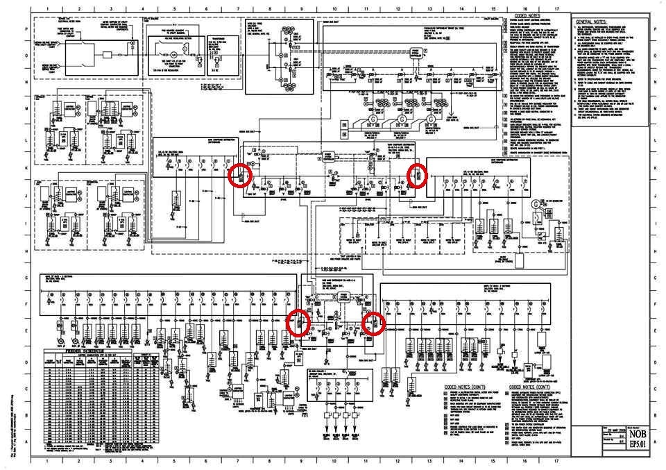
How to Calculate Power Factor Correction of Factory Load from Motor Schedule. using MS Excel Consider the scenario that you have plans for a new factory in front of you and have been asked to
APPLICATION OF POWER FACTOR CORRECTION CAPACITORS Understanding Power Factor As with any equipment, an electrical system handles its job to some degree of efficiency ranging from poor to excellent. The measure of electrical efficiency is known as Power Factor. The motors and other inductive equipment in a plant require two kinds of electric power. One type is working power, …
power factor signals efficient utilization of electrical power, while a low power factor indicates poor utilization of electrical power To determine power factor (PF), divide working power (kW) by apparent power (kVA) . In a linear or sinusoidal system, the result is also referred to as the cosine θ.. For example, if you had a boring mill that was operating at 100 kW and the apparent power
Let us illustrate the power relations in an a.c. circuit with an example. Suppose a Suppose a circuit draws a current of 10 A at a voltage of 200 V and its p.f. is 0·8 lagging.
kVA, kVAR, kW, Apparent Power vs. True Power Calculations Measurements Power Factor Correction Capacitors System Impacts I2 R losses, Chapter 9 NEC Equipment sizing Power Factor Charges Problems with adding Caps Harmonic resonance Volt rise Power Factor vs Load Factor. What is Power Factor Power Factor is the cosine of the phase angle between current and voltage. Power Factor …
Calculating power factor As was mentioned before, the angle of this “power triangle” graphically indicates the ratio between the amount of dissipated (or consumed) power and the amount of
Example calculation. In a plant with active power equal to 300 kW at 400 V and cosφ= 0.75, we want to increase the power factor up to 0.90. In the table 1 above, at the intersection between the row “initial cosφ” 0.75 with the column “final cosφ” 0.9, a value of 0.398 for the coefficient K is obtained.
White Paper Page 1 The ROI of Power Factor Correction an 2016 A comparative analysis of power factor correction with upgrading or installing new equipment.
For power factor correction of high-voltage power systems or large, For example, if the load power factor were as low as 0.7, the apparent power would be 1.4 times the real power used by the load. Line current in the circuit would also be 1.4 times the current required at 1.0 power factor, so the losses in the circuit would be doubled (since they are proportional to the square of the
Power Factor Correction Transformers & Power Factor Calculations Power Transmission and Distribution / By Asheesh / Electrical Engineering All electrical equipment works with a degree of efficiency which may be poor or excellent.
Power Capacitors Ltd Supported Technical Documentation

Calculating power factor IDC-Online
The size of capacitor in kVAR is the kW multiplied by factor in table to improve from existing power factor to proposed power factor. Check the others Examples below. Check the others Examples …
Example#1: Assume that the power factor of a 630 kVA oil distribution transformer which supplies a load equal to 60% of its rated power is to be corrected. Calculate the
Understanding power factor 03 Power factor correction 05 Implementing power factor correction techniques 06 poor power factor example shown in Figure 1. In Figure 2A, with the capacitors, the angle is reduced, therefore the total power drawn from the supply is less. However, there is still a ‘lagging’ power factor. Figure 2B shows how the addition of more capacitance brings the total
Try out our power factor correction sizing calculator. Just input the active power in (kW) and the system voltage, the existing measured or calculated power factored and the require power factor …
Figure G16 gives the values of correction factor k4 for different configurations of unburied cables or conductors, grouping of more than one circuit or multi-core cables. Arrangement (cables touching)
of Power Factor Correction Peter Riese Information • Tables • Formulas Everything on the subject of power factor correction for engineers and users. 2. 3 FRAKO power factor correction (PFC) systems make a major contribution to achieving energy efficiency and reducing CO 2 emissions, and are thus an indispensable component of modern electrical installations. At present-day electrical power
Power Factor Correction Desired Power Factor in percent The formula to calculate the required kVAR is: Factor from Table 1 below x kW = kVAR of capacitors required. EXAMPLE: A small machine tool plant used an average of 100 kW with an existing power factor of 80%. Their desired power factor is 95%. The kVAR of capacitors necessary to raise the power factor to 95% is found by using Table 1
ECE-311 (ECE, NDSU) Lab 6 – Experiment Power 2: power-factor correction 1. Objective The objective of this experiment is to study the concept of power factor. Calculation and correction of the power factor of an electrical load are investigated. 2. Introduction In ac circuits, power factor (pf) affects the price at which the power company can deliver power to your house (or factory or farm
6 Calculation of the power factor Power factor correction and harmonic filtering in electrical plants 3 1 Generalities on power factor correction 1 Generalities on power factor correction In alternating current circuits, the current absorbed by a load can be represented by two components: • the active component I R, in phase with the supply voltage, is directly related to the output (and
4 August 2007 The example calculation below is for a PG&E customer to increase power factor from 70% to 90%. Values given are average for a year, not monthly or season specific.

Example dc Drive Current Waveform and Harmonic Spectrum. The dc drives also generate significant harmonic currents. Figure 1 is an example current waveform and harmonic spectrum for a dc drive load. The harmonics make power factor correction more complicated. Power factor correction capacitors can cause resonant conditions which magnify the harmonic currents and cause excessive distortion
power and power factor, calculate the indicated quantity. 5. State in writing two common methods of improving the power factor. January 1990 1 ITPO.OI. PI 26.35-2 1.0 INTRODUCTION This lesson introduces the student to the concept of: (a) active, reactive and apparent power. (b) power factor. le} methods of power factor correction. 2.0 POWER Power is the rate at which energy is consumed in …
One common example of reactive power can be seen in an unloaded AC motor. When all load is removed from the motor, one might expect the no-load current to drop near zero. In truth, however, the no-load current will generally show a value between 25% and 30% of full load current. This is because of the con-tinuous demand for magnetizing current by any inductive load. Active power is the power
CALCULATORS FOR USE IN POWER FACTOR CORRECTION. The calculators provided on this web page may be utilized in the design and application of power …
Power Factor Take for example a motor with a current draw of 100 Amps and a power factor of 0.75 the resistive component of the current is 75 Amps and this is what the
6 Calculation of the power factor Power factor correction and harmonic filtering in electrical plants 3 P ϕ Q ϕ S I R V I Q I 1 Generalities on power factor correction 1 Generalities on power factor correction In alternating current circuits, the current absorbed by a load can be represented by two components: • the active component I R, in phase with the supply voltage, is directly
this approach allows easy calculation of the rating of power factor correction equipment. Power Factor Correction Feature Adjustment factor Automatic monitoring and targeting with alarms for out of range values1 0.050 Power factor correction to achieve a whole building power factor >0.902 0.010 Power factor correction to achieve a whole building power factor >0.952 0.025 Notes:1. Automatic
ECE-311 (ECE NDSU) Lab 6 Experiment Power 2 power-factor
The power factor of a load, which may be a single power-consuming item, or a number of items (for example an entire installation), is given by the ratio of P/S i.e. kW divided by kVA at any given moment. – island mist wine kits instructions
How to Calculate Power Factor Correction of Mixed Load
Power Factor Correction Calculator — Electrical Engineers


–

Example calculation. In a plant with active power equal to 300 kW at 400 V and cosφ= 0.75, we want to increase the power factor up to 0.90. In the table 1 above, at the intersection between the row “initial cosφ” 0.75 with the column “final cosφ” 0.9, a value of 0.398 for the coefficient K is obtained.
Power Factor Correction Calculator — Electrical Engineers
Power Capacitors Ltd Supported Technical Documentation
POWER AND POWER FACTOR OBJECTIVES
Calculating power factor As was mentioned before, the angle of this “power triangle” graphically indicates the ratio between the amount of dissipated (or consumed) power and the amount of
How to Calculate Power Factor Correction of Mixed Load
Calculating power factor As was mentioned before, the angle of this “power triangle” graphically indicates the ratio between the amount of dissipated (or consumed) power and the amount of
ECE-311 (ECE NDSU) Lab 6 Experiment Power 2 power-factor
Power Capacitors Ltd Supported Technical Documentation
Power Factor Correction Desired Power Factor in percent The formula to calculate the required kVAR is: Factor from Table 1 below x kW = kVAR of capacitors required. EXAMPLE: A small machine tool plant used an average of 100 kW with an existing power factor of 80%. Their desired power factor is 95%. The kVAR of capacitors necessary to raise the power factor to 95% is found by using Table 1
Power factor correction and harmonic filterin
Calculating power factor IDC-Online
Power Capacitors Ltd Supported Technical Documentation
this approach allows easy calculation of the rating of power factor correction equipment. Power Factor Correction Feature Adjustment factor Automatic monitoring and targeting with alarms for out of range values1 0.050 Power factor correction to achieve a whole building power factor >0.902 0.010 Power factor correction to achieve a whole building power factor >0.952 0.025 Notes:1. Automatic
NEPSI Power Factor and General Power System Analysis
ECE-311 (ECE NDSU) Lab 6 Experiment Power 2 power-factor
For power factor correction of high-voltage power systems or large, For example, if the load power factor were as low as 0.7, the apparent power would be 1.4 times the real power used by the load. Line current in the circuit would also be 1.4 times the current required at 1.0 power factor, so the losses in the circuit would be doubled (since they are proportional to the square of the
POWER AND POWER FACTOR OBJECTIVES
Power Capacitors Ltd Supported Technical Documentation
Calculating power factor As was mentioned before, the angle of this “power triangle” graphically indicates the ratio between the amount of dissipated (or consumed) power and the amount of
Power Capacitors Ltd Supported Technical Documentation
4 August 2007 The example calculation below is for a PG&E customer to increase power factor from 70% to 90%. Values given are average for a year, not monthly or season specific.
ECE-311 (ECE NDSU) Lab 6 Experiment Power 2 power-factor
Power Factor Correction Calculator — Electrical Engineers
NEPSI Power Factor and General Power System Analysis
Power Factor Correction Desired Power Factor in percent The formula to calculate the required kVAR is: Factor from Table 1 below x kW = kVAR of capacitors required. EXAMPLE: A small machine tool plant used an average of 100 kW with an existing power factor of 80%. Their desired power factor is 95%. The kVAR of capacitors necessary to raise the power factor to 95% is found by using Table 1
POWER AND POWER FACTOR OBJECTIVES
Calculating power factor IDC-Online
Try out our power factor correction sizing calculator. Just input the active power in (kW) and the system voltage, the existing measured or calculated power factored and the require power factor …
Power factor correction and harmonic filterin
How to Calculate Power Factor Correction of Mixed Load
ECE-311 (ECE NDSU) Lab 6 Experiment Power 2 power-factor
Power Factor Correction Transformers & Power Factor Calculations Power Transmission and Distribution / By Asheesh / Electrical Engineering All electrical equipment works with a degree of efficiency which may be poor or excellent.
Power factor correction and harmonic filterin
Power Capacitors Ltd Supported Technical Documentation
Power Factor Correction Calculator — Electrical Engineers
Power Factor Correction Desired Power Factor in percent The formula to calculate the required kVAR is: Factor from Table 1 below x kW = kVAR of capacitors required. EXAMPLE: A small machine tool plant used an average of 100 kW with an existing power factor of 80%. Their desired power factor is 95%. The kVAR of capacitors necessary to raise the power factor to 95% is found by using Table 1
ECE-311 (ECE NDSU) Lab 6 Experiment Power 2 power-factor
Calculating power factor IDC-Online
this approach allows easy calculation of the rating of power factor correction equipment. Power Factor Correction Feature Adjustment factor Automatic monitoring and targeting with alarms for out of range values1 0.050 Power factor correction to achieve a whole building power factor >0.902 0.010 Power factor correction to achieve a whole building power factor >0.952 0.025 Notes:1. Automatic
NEPSI Power Factor and General Power System Analysis
ECE-311 (ECE NDSU) Lab 6 Experiment Power 2 power-factor
POWER AND POWER FACTOR OBJECTIVES
Example calculation. In a plant with active power equal to 300 kW at 400 V and cosφ= 0.75, we want to increase the power factor up to 0.90. In the table 1 above, at the intersection between the row “initial cosφ” 0.75 with the column “final cosφ” 0.9, a value of 0.398 for the coefficient K is obtained.
ECE-311 (ECE NDSU) Lab 6 Experiment Power 2 power-factor
How to Calculate Power Factor Correction of Mixed Load
Calculating power factor As was mentioned before, the angle of this “power triangle” graphically indicates the ratio between the amount of dissipated (or consumed) power and the amount of
How to Calculate Power Factor Correction of Mixed Load
Power Capacitors Ltd Supported Technical Documentation
Example dc Drive Current Waveform and Harmonic Spectrum. The dc drives also generate significant harmonic currents. Figure 1 is an example current waveform and harmonic spectrum for a dc drive load. The harmonics make power factor correction more complicated. Power factor correction capacitors can cause resonant conditions which magnify the harmonic currents and cause excessive distortion
POWER AND POWER FACTOR OBJECTIVES
APPLICATION OF POWER FACTOR CORRECTION CAPACITORS Understanding Power Factor As with any equipment, an electrical system handles its job to some degree of efficiency ranging from poor to excellent. The measure of electrical efficiency is known as Power Factor. The motors and other inductive equipment in a plant require two kinds of electric power. One type is working power, …
POWER AND POWER FACTOR OBJECTIVES
Power factor correction and harmonic filterin
Calculating power factor IDC-Online
Example dc Drive Current Waveform and Harmonic Spectrum. The dc drives also generate significant harmonic currents. Figure 1 is an example current waveform and harmonic spectrum for a dc drive load. The harmonics make power factor correction more complicated. Power factor correction capacitors can cause resonant conditions which magnify the harmonic currents and cause excessive distortion
NEPSI Power Factor and General Power System Analysis
of Power Factor Correction Peter Riese Information • Tables • Formulas Everything on the subject of power factor correction for engineers and users. 2. 3 FRAKO power factor correction (PFC) systems make a major contribution to achieving energy efficiency and reducing CO 2 emissions, and are thus an indispensable component of modern electrical installations. At present-day electrical power
NEPSI Power Factor and General Power System Analysis
The size of capacitor in kVAR is the kW multiplied by factor in table to improve from existing power factor to proposed power factor. Check the others Examples below. Check the others Examples …
Power Capacitors Ltd Supported Technical Documentation
Example calculation. In a plant with active power equal to 300 kW at 400 V and cosφ= 0.75, we want to increase the power factor up to 0.90. In the table 1 above, at the intersection between the row “initial cosφ” 0.75 with the column “final cosφ” 0.9, a value of 0.398 for the coefficient K is obtained.
ECE-311 (ECE NDSU) Lab 6 Experiment Power 2 power-factor
POWER AND POWER FACTOR OBJECTIVES
Power Capacitors Ltd Supported Technical Documentation
Example#1: Assume that the power factor of a 630 kVA oil distribution transformer which supplies a load equal to 60% of its rated power is to be corrected. Calculate the
How to Calculate Power Factor Correction of Mixed Load
Calculating power factor IDC-Online
Power Factor Correction Calculator — Electrical Engineers
Power Factor Correction Transformers & Power Factor Calculations Power Transmission and Distribution / By Asheesh / Electrical Engineering All electrical equipment works with a degree of efficiency which may be poor or excellent.
Power factor correction and harmonic filterin
Power Factor Take for example a motor with a current draw of 100 Amps and a power factor of 0.75 the resistive component of the current is 75 Amps and this is what the
Power Capacitors Ltd Supported Technical Documentation
POWER AND POWER FACTOR OBJECTIVES
ECE-311 (ECE NDSU) Lab 6 Experiment Power 2 power-factor
power factor signals efficient utilization of electrical power, while a low power factor indicates poor utilization of electrical power To determine power factor (PF), divide working power (kW) by apparent power (kVA) . In a linear or sinusoidal system, the result is also referred to as the cosine θ.. For example, if you had a boring mill that was operating at 100 kW and the apparent power
Calculating power factor IDC-Online
ECE-311 (ECE NDSU) Lab 6 Experiment Power 2 power-factor
Power Capacitors Ltd Supported Technical Documentation
Example calculation. In a plant with active power equal to 300 kW at 400 V and cosφ= 0.75, we want to increase the power factor up to 0.90. In the table 1 above, at the intersection between the row “initial cosφ” 0.75 with the column “final cosφ” 0.9, a value of 0.398 for the coefficient K is obtained.
Power Factor Correction Calculator — Electrical Engineers
Calculating power factor As was mentioned before, the angle of this “power triangle” graphically indicates the ratio between the amount of dissipated (or consumed) power and the amount of
Calculating power factor IDC-Online
The size of capacitor in kVAR is the kW multiplied by factor in table to improve from existing power factor to proposed power factor. Check the others Examples below. Check the others Examples …
NEPSI Power Factor and General Power System Analysis
Calculating power factor IDC-Online
How to Calculate Power Factor Correction of Mixed Load
The size of capacitor in kVAR is the kW multiplied by factor in table to improve from existing power factor to proposed power factor. Check the others Examples below. Check the others Examples …
Power Capacitors Ltd Supported Technical Documentation
How to Calculate Power Factor Correction of Mixed Load
The power factor of a load, which may be a single power-consuming item, or a number of items (for example an entire installation), is given by the ratio of P/S i.e. kW divided by kVA at any given moment.
Calculating power factor IDC-Online
Power Capacitors Ltd Supported Technical Documentation
One common example of reactive power can be seen in an unloaded AC motor. When all load is removed from the motor, one might expect the no-load current to drop near zero. In truth, however, the no-load current will generally show a value between 25% and 30% of full load current. This is because of the con-tinuous demand for magnetizing current by any inductive load. Active power is the power
Power Capacitors Ltd Supported Technical Documentation
For power factor correction of high-voltage power systems or large, For example, if the load power factor were as low as 0.7, the apparent power would be 1.4 times the real power used by the load. Line current in the circuit would also be 1.4 times the current required at 1.0 power factor, so the losses in the circuit would be doubled (since they are proportional to the square of the
Power Capacitors Ltd Supported Technical Documentation
How to Calculate Power Factor Correction of Mixed Load
POWER AND POWER FACTOR OBJECTIVES
power and power factor, calculate the indicated quantity. 5. State in writing two common methods of improving the power factor. January 1990 1 ITPO.OI. PI 26.35-2 1.0 INTRODUCTION This lesson introduces the student to the concept of: (a) active, reactive and apparent power. (b) power factor. le} methods of power factor correction. 2.0 POWER Power is the rate at which energy is consumed in …
Power Capacitors Ltd Supported Technical Documentation
Calculating power factor IDC-Online
POWER AND POWER FACTOR OBJECTIVES
White Paper Page 1 The ROI of Power Factor Correction an 2016 A comparative analysis of power factor correction with upgrading or installing new equipment.
Calculating power factor IDC-Online
APPLICATION OF POWER FACTOR CORRECTION CAPACITORS Understanding Power Factor As with any equipment, an electrical system handles its job to some degree of efficiency ranging from poor to excellent. The measure of electrical efficiency is known as Power Factor. The motors and other inductive equipment in a plant require two kinds of electric power. One type is working power, …
Power factor correction and harmonic filterin
POWER AND POWER FACTOR OBJECTIVES
Example dc Drive Current Waveform and Harmonic Spectrum. The dc drives also generate significant harmonic currents. Figure 1 is an example current waveform and harmonic spectrum for a dc drive load. The harmonics make power factor correction more complicated. Power factor correction capacitors can cause resonant conditions which magnify the harmonic currents and cause excessive distortion
Calculating power factor IDC-Online
Power factor correction and harmonic filterin
Power Capacitors Ltd Supported Technical Documentation
kVA, kVAR, kW, Apparent Power vs. True Power Calculations Measurements Power Factor Correction Capacitors System Impacts I2 R losses, Chapter 9 NEC Equipment sizing Power Factor Charges Problems with adding Caps Harmonic resonance Volt rise Power Factor vs Load Factor. What is Power Factor Power Factor is the cosine of the phase angle between current and voltage. Power Factor …
POWER AND POWER FACTOR OBJECTIVES
6 Calculation of the power factor Power factor correction and harmonic filtering in electrical plants 3 1 Generalities on power factor correction 1 Generalities on power factor correction In alternating current circuits, the current absorbed by a load can be represented by two components: • the active component I R, in phase with the supply voltage, is directly related to the output (and
Power factor correction and harmonic filterin
Power Factor Correction Desired Power Factor in percent The formula to calculate the required kVAR is: Factor from Table 1 below x kW = kVAR of capacitors required. EXAMPLE: A small machine tool plant used an average of 100 kW with an existing power factor of 80%. Their desired power factor is 95%. The kVAR of capacitors necessary to raise the power factor to 95% is found by using Table 1
POWER AND POWER FACTOR OBJECTIVES
How to Calculate Power Factor Correction of Mixed Load
NEPSI Power Factor and General Power System Analysis
Power Factor Correction Transformers & Power Factor Calculations Power Transmission and Distribution / By Asheesh / Electrical Engineering All electrical equipment works with a degree of efficiency which may be poor or excellent.
NEPSI Power Factor and General Power System Analysis
Power Factor Correction Transformers & Power Factor Calculations Power Transmission and Distribution / By Asheesh / Electrical Engineering All electrical equipment works with a degree of efficiency which may be poor or excellent.
ECE-311 (ECE NDSU) Lab 6 Experiment Power 2 power-factor